English
  日本語
日本語  한국어
한국어  français
  Deutsch
  Español
  русский
  العربية

Mar
Learn More
13

Creating design for aluminum components that will undergo CNC machining has to go beyond the fact of making a proper 3D model. A truly manufacturable design implies consideration of machine access, tool selection, material behavior, tolerances, and efficiency of manufacture of parts. Proper aluminum CNC machining design helps reduce unnecessary machining operations, improve part quality, and achieve more consistent production results.
The present engineering guide discusses the main aluminum CNC design guidelines for engineers and developers, mentioning such aspects as DFM principles, part geometry, wall thickness, pocket design, CAD specifications, machining tolerances and cost cutting measures. By implementing the described design principles at the earliest stages of development, an engineer facilitates the manufacturing, testing and scaling of aluminum CNC machined parts.
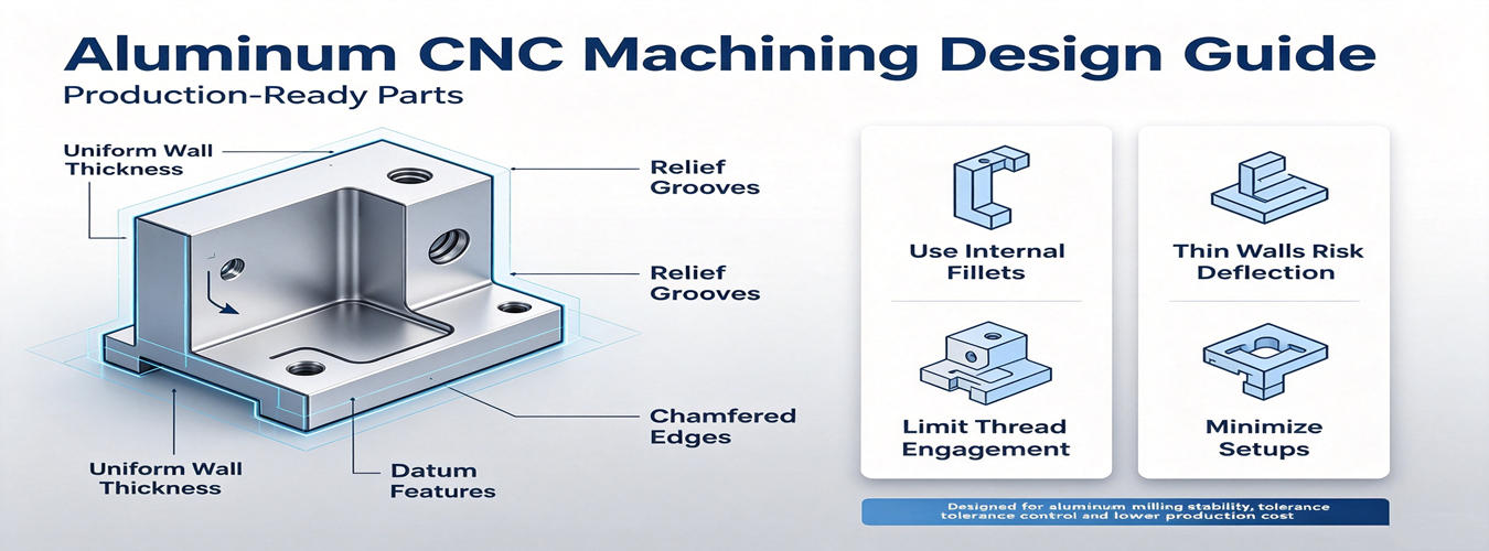
Aluminum CNC machining design means designing aluminum components with manufacturing considerations before the machining process starts. Unlike a design that is solely focused on function, CNC design considers the interaction of cutting tools, machines, fixtures, and inspection techniques with the part.
Good design decisions can have a huge impact on machining efficiency, precision, and total production cost for aluminum parts. Factors such as design features accessibility, material removal volume, wall thickness, corner geometry, and tolerances have an influence on manufacturability of a component.
A well-designed aluminum CNC part should consider:
Tool access for milling and turning operations
Appropriate geometry for standard cutting tools
Practical tolerances based on functional requirements
Suitable material selection and surface finishing needs
Scalability from prototype machining to production manufacturing
By adhering to the best practices in aluminum CNC design at the engineering stage, it is possible to avoid the common manufacturing problems of very high machining time, tool obstruction, vibration, and increased costs. For businesses that are making aluminum CNC parts, combining design factors with manufacturing know-how promotes the easiest transition from 3D computer model to a finished product. By integrating DFM principles with CNC machining services, engineers can create production-ready aluminum parts

Design for Manufacturability (DFM) is the starting point for successful aluminum CNC machining design. The focus of DFM is on the design of aluminum parts that are functionally correct and are also easier, faster, and cheaper to manufacture. During the design stage, it is highly advantageous to use DFM principles in the design process as it enables reducing machining complexity and improving repeatability in the manufacturing of CNC aluminum components.
When developing CNC aluminum part design, engineers must bear in mind the interdependence of shape features of parts with machining processes. The tasks that require special tools, require multiple setups, or are hard to reach tend to significantly increase manufacturing cost and manufacturing time.
Key aluminum machining design rules include:
| Design Consideration | Recommended Approach |
| Tool accessibility | Avoid features that require complex tool angles or special tooling |
| Part geometry | Use simple, machining-friendly shapes whenever possible |
| Internal corners | Apply suitable radii based on standard cutting tools |
| Wall thickness | Maintain sufficient thickness to prevent vibration and deformation |
| Tolerances | Specify tight tolerances only for functional requirements |
| Machining setup | Reduce unnecessary repositioning to improve accuracy |
By adhering to the best practices in aluminum CNC design, manufacturers have the opportunity to smoothly implement their machining techniques before starting the manufacturing process. This holds true for those projects where the designs pass the prototype development stage and go into mass production, since the smallest of modifications in the design signify massive savings in cost and efficiency of manufacturing operations.
When DFM principles are amalgamated with the knowledge of CNC engineering, the engineers manage to create production-ready aluminum parts and meeting the properties they need but easy to produce.
The geometry of the part is one of the utmost factors affecting the efficiency, precision, and cost of CNC processes. A well-designed aluminum CNC part design should consider how cutting tools access features, how much material needs to be removed, and how the part will remain stable during machining.
The wrong choice of geometry may result in unnecessary setups, long machining time, wear of the tool, and increased manufacturing costs. This is why following practical guidelines in terms of aluminum CNC design will allow engineers to create simpler components that can be manufactured while preserving their performance.

It is vital to keep the optimal thickness to ensure machining of aluminum parts. Thin walls lead to reduced rigidity of the parts, which increases the chances of vibrations and distortions during the cutting process.
For thin wall aluminum machining design, engineers should consider:
Avoiding unnecessarily thin structures
Increasing wall thickness where structural strength is required
Reducing cutting forces through optimized geometry
Supporting thin features with ribs or reinforced structures when needed
Deep pockets and complex cavities require longer cutting tools, which can increase tool deflection and reduce machining stability. Optimizing pocket depth and width helps improve tool performance and surface quality.
Recommended practices include:
Avoiding excessively deep narrow pockets
Using standard tool sizes where possible
Designing accessible internal features
Since CNC milling tools are round, the internal corners would be challenging to cut properly. Creating suitable corner radii in aluminum CNC increases the ability of the tool to move freely, shorter processing time, and improved surface quality.
In addition, larger internal radii can minimize the need for smaller tools, thus increasing stability of processing and efficiency of manufacturing.
There must be compliance with accepted design standards for functional elements, such as holes, threads, bosses, and ribs. Effective position of elements allows ensuring better accessibility and lowering complexity of manufacturing process.
For example:
Avoid placing holes too close to part edges
Use standard thread sizes when possible
Design ribs to improve strength without creating unnecessary machining challenges
Consider tool access when adding complex features
Applying these aluminum machining design considerations during the early design stage helps create more reliable CNC parts and supports a smoother transition from prototype machining to production manufacturing. Find more details about thin wall aluminum machining.

The milling strategy has a direct impact on the manufacturability, accuracy, and cost of aluminum components. When developing aluminum CNC milling design, engineers should consider machining access, tool movement, part orientation, and the number of required setups.
A carefully designed and planned milling provides manufacturers with an opportunity to employ standard cutting tools, participate in the process of eliminating unnecessary processes, and be assured of achieved quality during the manufacturing process.
The required machining approach depends on part complexity and feature accessibility.
| Machining Method | Design Consideration |
| 3-axis CNC machining | Suitable for parts with accessible features on standard planes |
| 5-axis CNC machining | Ideal for complex geometries, angled surfaces, and reduced setups |
5-axis CNC machining of aluminum is advantageous for parts with a multitude of angled surfaces and surfaces that are deep and/or complex because it allows the tool to reach areas more easily and cuts down on the need for repositioning.
In aluminum milling circulars, tool approach must be considered as per the design. Designs that involve angles for tools that are not typical, long cutting tools, and multiple fixtures can create complications in manufacturing.
Recommended practices include:
Keep critical features accessible to standard cutting tools
Minimize deep narrow cavities
Reduce unnecessary machining orientations
Consider fixture requirements during design
By optimizing milling geometry early, engineers can create more efficient CNC machining processes and improve the transition from prototype parts to production manufacturing.
For complex aluminum components requiring advanced multi-axis machining, Falcon CNC Swiss provides precision aluminum machining solutions from prototype development to production.
A manufacturing-ready CAD model is important for effective CNC aluminum production. Prior to initiation of manufacturing works, engineers must deliver proper design data that contains information about part geometries, material characteristics, required dimensions, and functioning specifications.
Properly executed aluminum CNC CAD design enables manufacturers to make decisions with regard to possibility of producing a particular part, select appropriate tooling, and optimize a manufacturing process prior to material cutting.
Recommended CAD and Drawing Information
For CAD design for aluminum machining, engineers should include:
| Design Information | Purpose |
| 3D CAD model | Defines part geometry and machining features |
| 2D engineering drawing | Provides dimensions and manufacturing requirements |
| Material specification | Confirms aluminum alloy selection |
| Tolerance requirements | Identifies critical functional dimensions |
| Surface finish requirements | Defines appearance and performance needs |
| Thread and hole specifications | Ensures correct machining features |
Common file formats such as STEP, IGES, and native CAD files allow manufacturers to review part geometry and prepare CNC programming efficiently.
Clear technical drawings should define only necessary requirements. Over-specifying dimensions or applying unnecessary tight tolerances can increase machining difficulty and production cost.
Important drawing elements include:
Datum references
Critical dimensions
General tolerances
Surface finish symbols
Special manufacturing notes
Following proper aluminum CNC drawing requirements allows engineers and manufacturers to collaborate more effectively, improving the transition from initial design to finished CNC aluminum components.

The process of specifying surface finish requirements and tolerances becomes a significant part of aluminum CNC machining structure design. Although CNC machining generates accurate and precise components, being overly stringent in specifying tolerances in all component features may lead to high inspection needs and expenses.
It is preferable to apply the criteria of noting functional features for assembly, operation, or performance purposes where clear cut tolerances have to be applied while allowing standard tolerances in the rest of the features.
When preparing aluminum CNC design tolerances, engineers should consider:
Functional requirements of the component
Assembly relationships between parts
Material characteristics of aluminum alloys
Machining process capability
Inspection requirements
Common tolerance considerations include:
Dimensional accuracy
Hole and shaft fits
Flatness and parallelism
Feature location accuracy
For precision applications, tighter tolerances may be required, but they should be applied selectively to critical areas rather than the entire component.
Surface finish affects both appearance and functional performance. During aluminum CNC surface finish planning, designers should consider whether the part requires:
Standard machined finish
Anodized surface treatment
Enhanced cosmetic appearance
Improved wear or corrosion resistance
Clear surface finish specifications help manufacturers select appropriate machining parameters and post-processing methods. For detailed information about aluminum machining accuracy requirements, see our Aluminum Machining Tolerance Guide.
Appropriate material selection is necessary for aluminum CNC machining process since various types of aluminum alloys differ in strength, machinability, toughness, and finishing capabilities. Proper selection of the alloy improves the chances of the obtained parts to meet and fulfill necessary requirements for performance and the required manufacturing.
Generally speaking, engineers involved in CNC aluminum manufacturing should try to combine mechanical efficiency and effective machining. Choosing a material that is too complicated for machining may prolong production, while selecting an unsuitable alloy may negatively affect the properties of the manufactured product.
Common aluminum alloys used for CNC machining include:
| Aluminum Alloy | Key Characteristics | Common Applications |
| 6061 Aluminum | Excellent machinability, balanced strength, good corrosion resistance | General CNC parts, housings, brackets |
| 7075 Aluminum | Higher strength and hardness | Aerospace components, high-performance parts |
| 2024 Aluminum | High strength and fatigue resistance | Structural and aerospace applications |
6061 aluminum is an excellent aluminum alloy for CNC machining due to its compelling balance between price, machining properties, and performance. Therefore, it is one of the most used alloys for the prototype and production parts.
Conversely, if there is a demand for better mechanical performance, the aluminum alloy 7075 may be used. Although, the material choice has to depend on the requirements of the manufactured component in use. Choosing the right aluminum alloy at the early stages of the design process increases machining productivity and reduces the risk of unplanned accidents happening during production.
The design process is a key factor in determining the total cost of aluminum CNC machining. While CNC techniques are able to offer great flexibility in terms of designing custom aluminum products, complex designs lead to longer machining times, additional tool requirements, extra setup processes, and higher costs of inspection.
A design that is manufacturing-friendly helps minimize unnecessary operations without losing functionality. Engineers can save costs by taking machining criteria into consideration as early as possible instead of making changes to designs after production has already started.
Key design factors that influence aluminum CNC part cost include:
| Design Factor | Cost Impact |
| Complex geometry | Requires additional programming and machining operations |
| Deep pockets and thin walls | Increases tooling challenges and machining time |
| Tight tolerances | Requires additional process control and inspection |
| Multiple setups | Increases labor and fixture requirements |
| Special finishes | Adds additional processing steps |
In order to cut down machining costs, a designer should focus on the functional requirements of a project, use standard dimensions of the tool for the project, eliminate any unnecessary complexity, and provide tolerances only when necessary.
For both prototype and production processes, early collaboration between engineers and manufacturers opens up possibilities for making the designs less complicated without affecting their performance. Thus, manufacturability is increased and the transition from CAD to finished product becomes more efficient.
By implementing practical aluminum machining design rules, businesses can stabilize the balance between performance, production efficiency, and manufacturing costs.

It is important to take a design approach that meets the requirements of both the first development and future manufacturing when completing a successful CNC aluminum project. What may work for a single prototype will require adjustments for the subsequent production process. The idea is to design in a way that facilitates transition from testing phase to production phase.
For aluminum CNC prototype parts, engineers can validate product concepts, evaluate functionality, and identify potential design improvements before committing to larger production quantities. During this stage, manufacturers can review machining accessibility, material selection, tolerances, and finishing requirements.
When moving toward aluminum CNC low volume production or larger manufacturing runs, design optimization becomes increasingly important. Production-ready designs should focus on:
Stable machining processes
Repeatable dimensions
Efficient tool paths
Reduced unnecessary operations
Consistent inspection requirements
By considering production requirements early, companies can reduce redesign risks and improve manufacturing efficiency. Falcon CNC Swiss supports customers from prototype development through production manufacturing, providing engineering assistance and precision CNC machining solutions for complex aluminum components. For complete aluminum machining support from design review to manufacturing, explore our custom aluminum machining services.
A manufacturable design is the foundation of successful CNC production. Falcon CNC Swiss works with engineers and OEM teams to review part designs, optimize machining feasibility, and support the transition from prototype development to production manufacturing.
Upload your CAD files and drawings for an engineering review.
The appropriate wall thickness will depend on the size of the part, geometry, machining methods used, and application needs. It is better to avoid very thin walls as they contribute to vibrations and deformations during machining. Early design reviews with a CNC manufacturer, especially for complicated thin-walled details, can facilitate mass production.
Design decisions influence aluminum CNC machining prices a lot. By using standard tools, less complicated shapes, non-rigid tolerances, and reducing setups, you can save on costs while keeping the same product properties.
The manufacturer will need a CAD design in a 3-D CAD format like STEP or IGES along with the technical drawings that contain all requirements related to dimensions, tolerance, material, thread type, and finishing.
6061 aluminum is very popular for general CNC production thanks to its good machinability and good balance of qualities. 7075 aluminum is a material of choice for applications that require more strength.
Yes, a properly designed aluminum component can go from aluminum CNC prototypes as well as low-volume and large-scale manufacture to mass production once designs are approved and processes optimized.